LH-TC Energy coupling device
Energy Coupling Device
The energy coupling device is a collection of multiple connection types on a single frame or housing, and can be configured according to specific specifications. It can meet the multi-function and frequent plug requirements, integrating power, signal, data, fiber, liquid and pneumatic systems. Suitable for applications which require combining electrical, power and pneumatic connections together.
.png)
High stability;
High reliability
.png)
Ultra-high plug-life
.png)
Strong current carrying capacity
.png)
Strong resistance to vibration and impact
Product introduction
| X, Y direction tolerance |
±4mm |
| Floating angle |
±1.5° |
| Position repeatability |
±0.1mm |
Φ 1.6 Signal Module
Table
 |
| Mechanical parameters: |
|
| Insertion force [N] |
1 |
| Pullout force [N] |
0.5 |
| Mechanical life [times] |
≥100000 |
| Jack type |
Springtac TM |
| Electrical parameters: |
|
| Maximum continuous current [A] |
13 |
| Instantaneous current [A] |
25 |
| Contact resistance (max) [mΩ] |
25 |
| Wire specification [mm²] |
1.5 |
| Material/Coating |
Copper alloy/gold plating |
| Environmental protection requirements |
RoHS 2.0 |
|
Φ 4 Power Module
Table
.png) |
| Mechanical parameters: |
|
| Insertion force [N] |
6 |
| Pullout force [N] |
3 |
| Mechanical life [times] |
≥100000 |
| Jack type |
Springtac TM |
| Electrical parameters: |
|
| Maximum continuous current [A] |
25 |
| Instantaneous current [A] |
50 |
| Contact resistance (max) [mΩ] |
0,8 |
| Wire specification [mm²] |
4 |
| Material/Coating |
Copper alloy/gold plating |
| Environmental protection requirements |
RoHS 2.0 |
|
Φ 8 Power Module
Tabela
.png) |
| Mechanical parameters: |
|
| Insertion force [N] |
25 |
| Pullout force [N] |
15 |
| Mechanical life [times] |
≥100000 |
| Jack type |
Springtac TM |
| Electrical parameters: |
|
| Maximum continuous current [A] |
105 |
| Instantaneous current [A] |
210 |
| Contact resistance (max) [mΩ] |
0,35 |
| Wire specification [mm²] |
16/25/35 |
| Material/Coating |
Copper alloy/gold plating |
| Environmental protection requirements |
RoHS 2.0 |
|
Φ 14 Power Module
Tabela
.png) |
| Mechanical parameters: |
|
| Insertion force [N] |
40 |
| Pullout force [N] |
30 |
| Mechanical life [times] |
≥100000 |
| Jack type |
Springtac TM |
| Electrical parameters: |
|
| Maximum continuous current [A] |
400 |
| Instantaneous current [A] |
550 |
| Contact resistance (max) [mΩ] |
135 |
| Wire specification [mm²] |
50/70/95/120 |
| Material/Coating |
Copper alloy/gold plating |
| Environmental protection requirements |
RoHS 2.0 |
|
1000Mbps Network Module
Tabela
 |
| Termination methods |
Welded plate |
| Mechanical property: |
|
| Mechanical life [times] |
≥50000 |
| Vibration and shock |
GB/T 21563 Class I Level B requirements |
| Electrical property: |
|
| Rated voltage |
50V |
| Rated current |
4A |
| Voltage resistance |
500V |
| Contact resistance |
≤8mΩ |
| Work temperature |
-40 °C ~ 125 °C |
| Network performance |
1000 Mbps |
| Environmental protection requirements |
RoHS 2.0 |
|
Φ3 Two-core pneumatic&liquid module
Table
 |
| Used for coupling compressed air and coolant |
|
| Poles number |
2 |
| Diameter [mm] |
3 |
| Support block material |
POM |
| Max working pressure [bar] |
15 |
| Min working pressure [mbar] |
14 |
| Work temperature [°C] |
-15~90 |
| Sealing material |
NBR |
| Pipe outer diameter [mm] |
6 |
| Mechanical life [times] |
≥100000 |
|
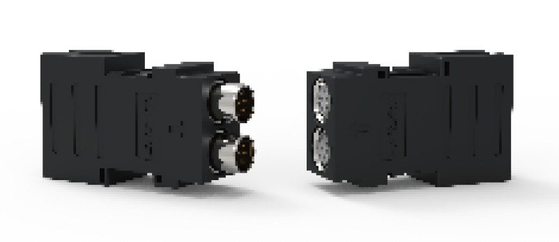
LT-F31-BI11 Energy Connector
 |
| Robot side PO: 1670 |
Tool side PO: 1671 |
| Provide energy connection between master station and slave station. |
| With X, Y, Z directional floating performance, eliminate docking error. |
| Modular design of medium unit, more flexible configuration. |
| Pass through medium such as electric power, data, i/o, air, liquid and other media. |
| Integrated tool side in position detection sensor. |
| Identification slave station number. |
|
| PO |
Model |
Configuration Parameters |
Weight (KG) |
| Robot Side |
1670 |
LT-F31-BI11-M |
2*PT3/8 self-sealed pneumatic ports
7/8-5 pin 9A independent bus power supply
M12-4-pin D-coded bus interface
Optional proximity switch
|
0.087 |
| Tool Side |
1671 |
LT-F31-BI11-T |
0.068 |
|
Compensation available:
- Compliance (X&Y-Axis): ±4mm
- Compliance (Z-Axis): +2mm
- Rotational Compliance: ±3°
- Min. Coupling Force: ≥1526N
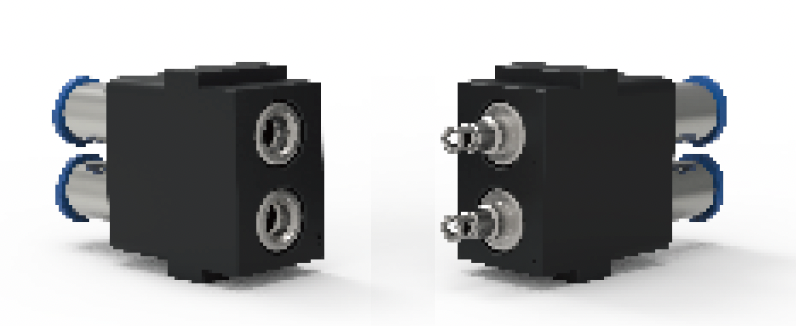
LT-F31C Energy Connector
|
| Optional max 4 x PT1/2 pneumatic ports or Liquid ports |
| Provide energy connection between master station and slave station |
| With X, Y, Z directional floating performance, eliminate docking error |
| Pass through medium such as electric power, data, i/o, air, liquid and other media |
| Integrated tool plate in position detection sensor |
| Optional driven way: Servo Motor or Pneumatic |
|
Compensation available:
- Compliance (X&Y-Axis): ±4mm
- Compliance (Z-Axis): +2mm
- Rotational Compliance: ±3°
- Min. Coupling Force: ≥1526N
Optional configuration:
| Signal IO: |
Industrial Bus Control: |
Servo motor connector: |
Electrical power: |
Air and liquid module: |
| 19~130 channel available |
-Profibus
-DeviceNet
-EtherNet
-Profinet
-CC-Link |
Available for ABB, KUKA, Fanuc, Yaskawa Servo motor interface
Servo + signal interface is optional |
7~35 channel available |
1~4 x PT1/2 pneumatic ports or Liquid ports available |
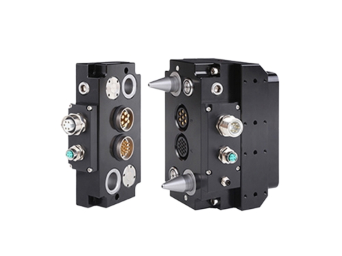
LT-F41 Energy Connector
Product section
| Lightweight design, compact structure. |
| Realize rapid connection of energy media such as current and communication. |
| With X, Y, Z directional floating performance, eliminate docking error. |
| To realize the quick docking of energy media such as pneumatic, liquid, current and communication, etc. |
| Optional 1~ 4 channels PT1/2 pneumatic port or water port. |
| Optional driven way: servo motor or cylinder. |
Compensation available:
- Compliance (X&Y-Axis): ±4mm
- Compliance (Z-Axis): +2mm
- Rotational Compliance: ±3°
- Min. Coupling Force: ≥1526N
LT-FEC Frame
LT-FEC Frame
The LT-FEC frame consists of two aluminum guide rails and an a fixed block with a grounding guide pin. The length of the guide rail depends on the configured module.
Advantages:
- Low maintenance cost
- High safety,
- Easy to operate
| Frame floating distance (FEC frame with Φ4 ground) |
| X/Y direction |
±1mm |
| Z direction |
±0.2mm |
| Floating angle |
±1° |
| Repeatability |
±0.1mm |
| Rail length [mm] |
48/72/96/144/156/174 |
Φ 4 Ground Pin
Table
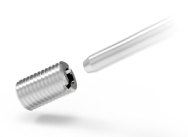 |
| Mechanical capacity: |
|
| Insertion and extraction force [N] |
4-8 |
| Mechanical life [usage times] |
≥100000 |
| Work Environment: |
|
| Work temperature |
-40°C~+125°C |
| Material/Coating/Appearance: |
|
| Pinhole parts/terminals |
Copper alloy, plated with silver |
| Standard and certification: |
|
| Environmental requirement |
RoHS 2.0 |
|
Water&Pneumatic Interface
Tabela
.png)
|
|
LH-L01BMH/LH-L01BTH |
LH-L01B06MH/LH-L01B06TH |
| Diameter [mm] |
8 |
6 |
| Max pressure [MPa] |
1.6 |
1.6 |
| Connection force without pressure [N] |
150 |
112.5 |
| Repulsive cross-sectional area [cm²] |
4.35 |
3.26 |
| Service life [million times] |
100 |
100 |
|
Hydraulic Interface
Tabela
.png)
|
|
LTPH08 |
LTPH08B |
LTPH12 |
LTPH12B |
| Diameter [mm] |
8 |
12 |
| The size of the interface |
G1/2 |
G3/4 |
| Connection force without pressure [N] |
163 |
210 |
| Socket/Plug repulsive cross-sectional area [cm²] |
2.14 |
4.52 |
| Flow [speed 5m/s] [l/min] |
16.49 |
37.31 |
| Insertion and extraction service life [number] |
≥100000 |
| Max pressure [MPa] |
16 |
25 |
16 |
25 |
|


.jpg)